Input files
The computational grid and boundary conditions for AeoLiS are specified through external input files called by the model parameter file aeolis.txt. The computational grid is defined with an x grid, y grid, and z grid. Boundary conditions for wind, wave, and tides are also specified with external text files. A list of additional grid and boundary files can be found in the table below. Each file is further defined below.
Input File |
File Description |
|---|---|
aeolis.txt |
File containing parameter definitions |
x.grd |
File containing cross-shore grid |
y.grd |
File containing alongshore grid (can be all zeros for 1D cases) |
z.grd |
File containing topography and bathymetry data |
veg.grd |
File containing initial vegetation density |
mass.txt |
File containing sediment mass data when using space varying grain size distribution |
wind.txt |
File containing wind speed and direction data |
tide.txt |
File containing water elevation data |
wave.txt |
File containing wave height and period data |
meteo.txt |
File containing meteorological time series data |
aeolis.txt
This is the parameter file for AeoLiS that defines the model processes and boundary conditions. Parameters in the file are specified by various keywords; each keyword has a pre-defined default value that will be used if it is not direclty specified in aeolis.txt (a list of default parameter values can be found in the Default settings tab on the left). Among the keywords in aeolis.txt are the keywords to define the external computational grid files (xgrid_file, ygrid_file, and bed_file) and external boundary condition files (tide_file, wave_file, wind_file, etc.). The different physical processes in AeoLiS can be turned on and off by changing the process keywords in aeolis.txt to T (True) and F (False). Example aeolis.txt parameters files can be found in the examples folder on the AeoLiS GitHub.
x.grd
The x.grd file defines the computational grid in the cross-shore direction defined in meters. In a 1-dimensional (1D) case, the file contains a single column of cross-shore locations starting at zero for a location of choice. In a 2-dimesional (2D) case, the file contains multiple columns (cross-shore positions) and rows (alongshore positions) where each value corresponds to a specific location in the 2D grid. The file can be renamed and is referenced from the parameters file with the xgrid_file keyword.
y.grd
This file defines the computational grid in the alongshore direction. In a 1D case, y.grd will contain a single column of zeros. In a 2D case, similar to the x.grd file, y.grd has multiple columns (cross-shore positions) and rows (alongshore positions) where each row, column position corresponds to a specific location in the 2D gird. x.grd and y.grd will always be the same size regardless of running a 1D or 2D simulation. As with the x.grd file, this file can be renamed and is referenced from the parameters file with the keyword: ygrid_file.
z.grd
The z.grd file provides the model with the elevation information for the computational grid defined in x.grd and y.grd. Similar to x.grd and y.grd, when running AeoLis in 1D the file contains a single column with the number of rows equal to the number of rows in x.grd and y.grd. In 2D cases, z.grd has multiple columns and rows of equal size to x.grd and y.grd. Elevation values in the file should be defined such that positive is up and negative is down. The file can be renamed and is referenced from the parameters file with the keyword: bed_file.
veg.grd
The veg.grd file is an optional grid providing initial vegetation coverage (density) at each position in the model domain defined in x.grd and y.grd. Similar to the grid files, if simulations are in 2D there will be multiple columns for each cross-shore position (x) and multiple rows for each alongshore position (y). The format of a 1D vegetation grid file can be seen below where each red dots represent vegetation cover at each cross-shore position.
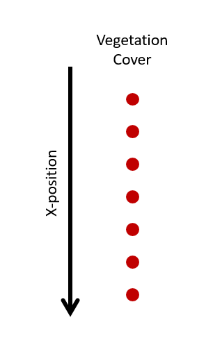
Fig. 5 File format for a 1D AeoLis vegetation grid. Each red dot is the vegetation density at a specific location in the computational grid.
mass.txt
The mass.txt file allows users to specify variations in grain size distribution in both horizontal and vertical directions. If the grain size distribution is constant throughout the model domain, multifraction sediment transport is possilbe without this file. The file contains the mass of each sediment fraction in each grid cell and bed layer. The file is formatted such that each row corresponds to a specific location in the computational domain and the columns are grouped by bed layers and each individual column represents a single sediment fraction present in the model domain. An infinite number of sediment fractions can be defined in the model; however, it should be noted the more sediment fractions present the longer the simulation time and larger the output files.
In a 1D case, the text file will have dimensions of number of cross-shore locations (x) by number of sediment fractions times the number of bed layers. For example if you have 200 cross-shore positions in your model domain and 4 different sediment fractions with 3 bed layers, your mass.txt file will contain a matrix of 200 rows by 12 columns. An example of a 1D mass.txt file can be seen below where each red dot represents a sediment fraction mass at a specific location in the model domain.
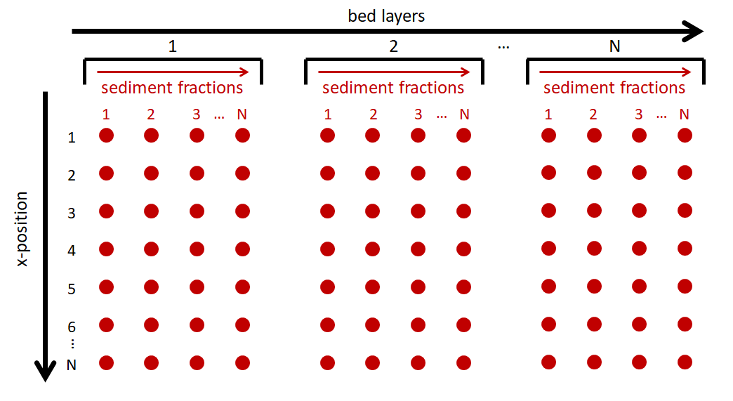
Fig. 6 File format for a 1D AeoLis mass for spatially variable grain size distributions. Each red dot is the mass for each sediment fraction at each location in the computational grid (x, y, bed layer).
In a 2D case, the mass.txt file will have dimensions of number of cross-shore positions (x) times the number of alongshore positions (x) by number of sediment fractions times the number of bed layers. The file will be formatted such that the columns are grouped by bed layer with all available sediment fractions present in each bed layer and rows are grouped by alongshore position with all cross-shore prositions given for each alongshore position. An visual example of a 2D mass.txt input file for AeoLis can be seen below.
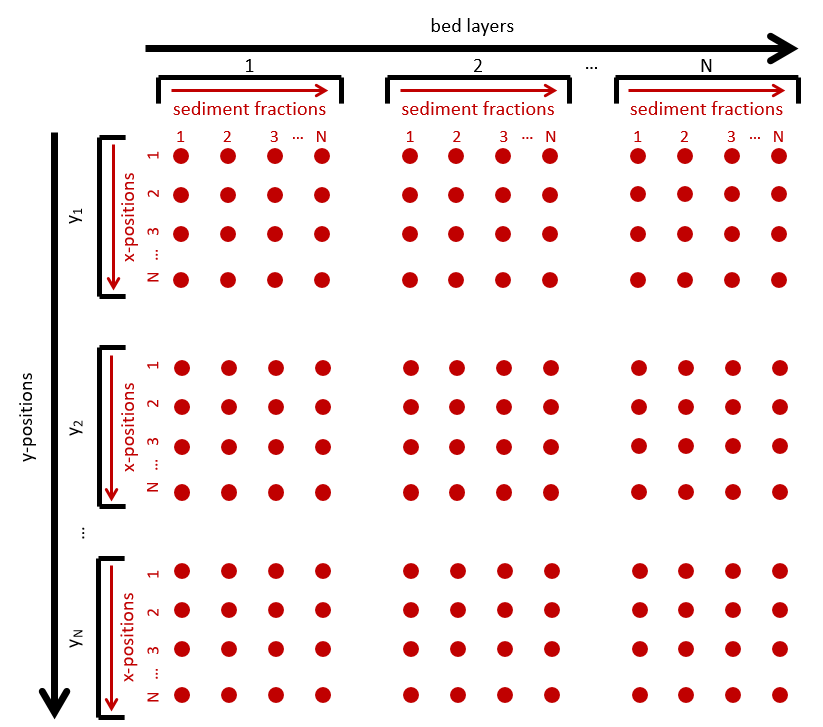
Fig. 7 File format for a 2D AeoLis mass file for spatially variable grain size distributions. Each red dot is the mass for each sediment fraction at each location in the computational grid (x, y, bed layer).
wind.txt
The wind.txt file provides the model with wind boundary conditions and is formatted similar to the tide.txt and wave.txt files. The first column is time in seconds from start, the second column is wind speed, and the third column is wind direction. The wind directions can be specified in either nautical or cartesian convention (specified in aeolis.txt with keyword: wind_convention). The format of this file can be seen below were each of the red dots represents a data value of time, wind speed, or wind direction. As AeoLiS is an aeolian sediment transport model, the wind boundary conditions are of particular importance.
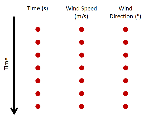
Fig. 8 File format for wind boundary conditions file for AeoLis input.
tide.txt
The tide.txt file contains the water elevation data for the duration of the simulation. It is formatted such that the first column is time in seconds and the second column is the water elevation data at each time step. An example of the file format can be seen below where each red dot represents a data value for time or water elevation.
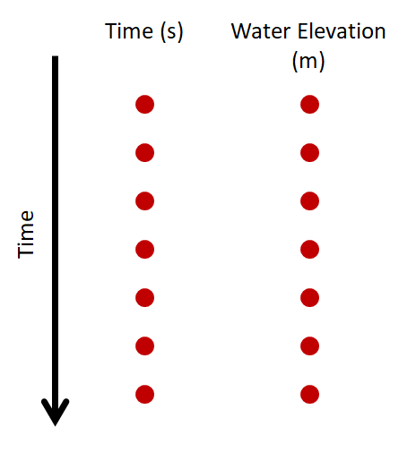
Fig. 9 File format for the water elevation conditions file for AeoLis input.
wave.txt
The wave.txt file provides the model with wave data used in AeoLiS for runup calculations. The file is formatted similar to tide.txt but has three columns instead of two. Here, the first column is time in seconds, the second column is wave height, and the third column is the wave period. The format of this file can be seen below where each red dot represents a data value.
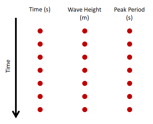
Fig. 10 File format for the wave conditions file for AeoLis input.
meteo.txt
The meteo.txt file contains meteorological data used to simulate surface moisture in the model domain (see Simulation of surface moisture in Model description on for surface moisture implementation in AeoLiS). This file is formatted similar to the other environmental boundary condition files (wind, wave, and tide) such that it contains a time series of environmental data read into AeoLiS through keyword specification. The keywords required to process surface moisture with evaporation and infiltration are process_moist = True, method_moist_process = surf_moisture, th_moisture = True, and meteo_file = meteo.txt (or name of file containing meteorological data). An example of the meteo.txt file can be seen in the figure below where each red dot represents a time series data value. The first column contains time (s), the second column is temperature (degrees C), the thrid column is precipitation (mm/hr), the fourth column is relative humidity (%), the fifth column is global radiation (MJ/$m^2$/day), and the sixth column is air pressure (kPa).
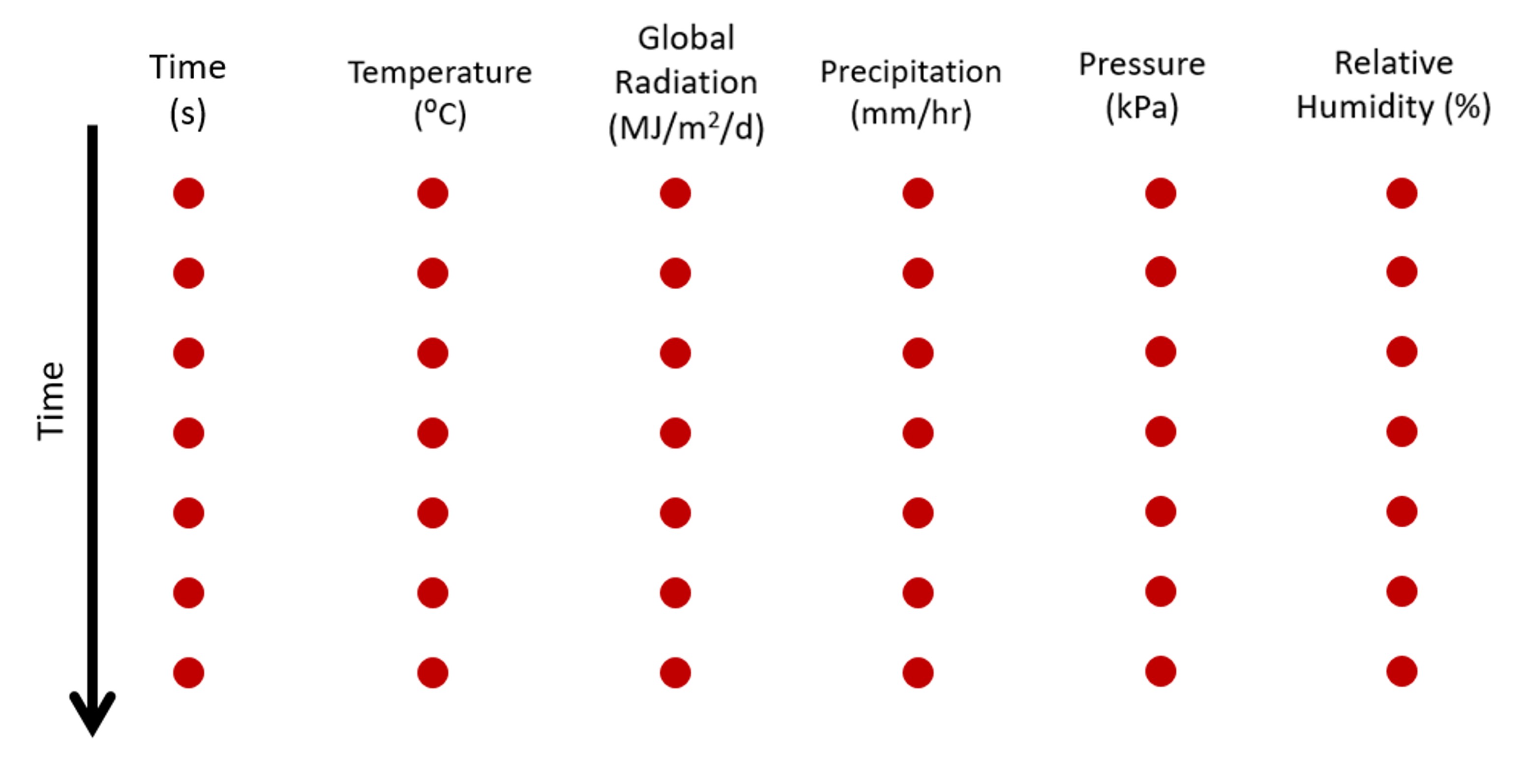
Fig. 11 File format for meteorological data used to simulate surface moisture in AeoLiS where each red dot represents a time series value.